MTCA ADCs
Content:
Our ADC cards
GHz ADCs: SP-Devices ADQ412AC
We have ADQ412AC-4G-MTCA digitizer cards for the experiment crates (Exp1, Exp2 and FL2Exp1):
( , )
The cards are connected via Patch panels to the Experimental endstations and can be operated with a jddd panel:
- NOTE: between ADC and Patch panel we have installed an and an additional 1dB attenuator
- for the influence of the Patch cable and the EMP protector see also this logbook entry

Impedance AC | 50 OHM |
Input voltage range | the complete range is about 1V for 4096 counts. Thus +- 0.5 V for baseline at 0V BUT the baseline can also be shifted ... |
|---|---|
Digitizer resolution | 12 bit |
4 CHANNELS MODE
Sampling rate | 2 * | GSPS |
Analog bandwidth | 2 | GHz |
2 CHANNELS MODE
Sampling rate | 4 * | GSPS |
Analog bandwidth | 1.3 | GHz |
* note that the sample rate is NOT locked to the FLASH repetition rate ! Thus there is a not integer number of samples between FLASH pulses. The sample rate also differs slightly from ADC card to ADC card. The rough spacing is 1993.846 samples between 2 pulses at 1 MHz for details ask the local contact.
ADC and DOOCS / DAQ
The HDF5 names for the ADC traces are depending on the beamline :
PG Beamline:
/FL1/Experiment/PG/ADQ412 GHz ADC/CH00/TD
/FL1/Experiment/PG/ADQ412 GHz ADC/CH01/TD
/FL1/Experiment/PG/ADQ412 GHz ADC/CH02/TD
/FL1/Experiment/PG/ADQ412 GHz ADC/CH03/TD
BL Beamlines:
/FL1/Experiment/BL1/ADQ412 GHz ADC/CH00/TD
/FL1/Experiment/BL1/ADQ412 GHz ADC/CH01/TD
/FL1/Experiment/BL1/ADQ412 GHz ADC/CH02/TD
/FL1/Experiment/BL1/ADQ412 GHz ADC/CH03/TD
/FL1/Experiment/BL2/ADQ412 GHz ADC/CH00/TD
/FL1/Experiment/BL2/ADQ412 GHz ADC/CH01/TD
/FL1/Experiment/BL3/ADQ412 GHz ADC/CH02/TD
/FL1/Experiment/BL3/ADQ412 GHz ADC/CH03/TD
and at FLASH2
FL24:/FL2/Experiment/MTCA-EXP1/ADQ412 GHz ADC/CH00/TD/FL2/Experiment/MTCA-EXP1/ADQ412 GHz ADC/CH01/TD/FL2/Experiment/MTCA-EXP1/ADQ412 GHz ADC/CH02/TD/FL2/Experiment/MTCA-EXP1/ADQ412 GHz ADC/CH03/TD
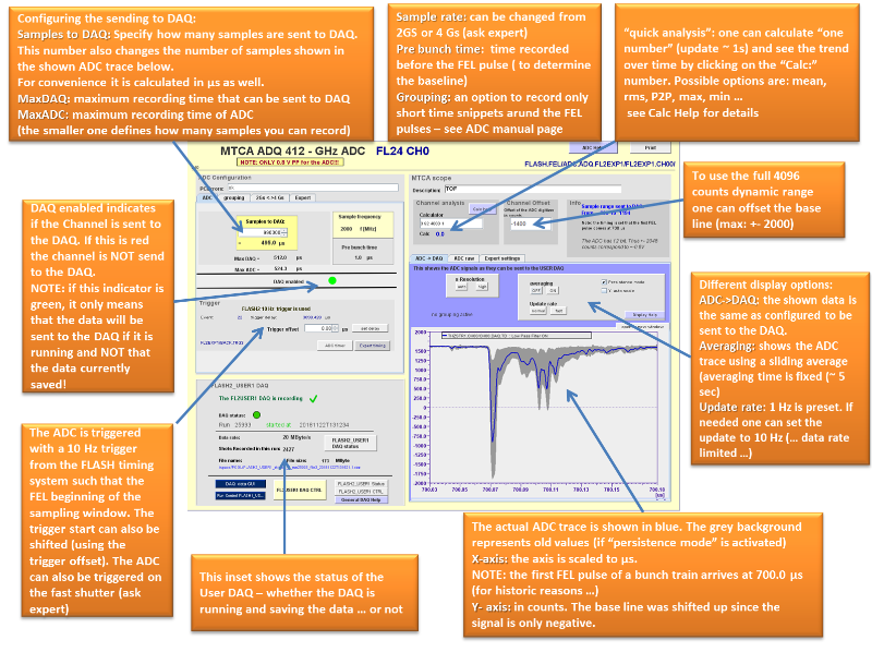
DOOCS prop : FLASH.FEL/ADC.ADQ.PG/EXP1.CH00/CH00.TD or CH00.DAQ.TD
here the CH00.TD is the full ADC trace as it is sampled ( typically several 100.000 samples per pulse train) while the CH00.DAQ.TD trace only has the number of samples which are sent to the DAQ OR if grouping is activated the CH00.DAQ.TD contains only the grouped spectra. To read the ADC trace with an online analysis program the CH00.DAQ.TD is preferable to use ...
DAQ channel: FLASH.FEL/ADC.ADQ.PG/EXP1.CH00
in addition there are also additional parameters saved like:
- sample frequency (in MHz)
- error (state)
- offset
Amplifiers for the GHZ ADCs
- we can offer amplifiers to either amplify small signals or to decouple setups which may deliver voltage peaks fro the ADCs.
- The available ADCs 5x, 10x, 20 x 50x and 100x
- The ADCs can be borrowed from Markus Braune
- The Amplifiers fit perfectly to the dynamic range of the GHz ADCs - here a
- There are also available that can be borrowed (link to internal page)

108 MHz ADCs: Struck SIS8300-L2D
There is one in each of the MTCAs in the hall: MTCA-EXP1 at PG/BL1, the other at BL2 and BL3.
They are 16 bit, 10 channel, 125 MS/s ADCs. Here is a link to the Struck website
50 Ohm input impedance, -1 V,...,+1 V default input range, analog signals can be routed to AC and DC input stage. The coupling is DC via op-amp (switching to AC transformer involves resoldering of SMD solder bridges).
Here is a trace of the first signal, a 1 MHz trigger connected from the x2timer board in the same MTCA:

Pulse energy server: Using the Struck SIS8300-L2D to detect only integrated values of pulses
FS-LA (Falko Peters) programmed a pulse detection server that automatically detects peaks in the signal and integrates the samples around the peak.
Things to set:
- Min peak height: threshold fro which on some signal is considered to be a peak. The actual peak is then determined as the maximum of the counts after the threshold
- pre and post peak integration time: how much ns to be integrated before and after the peak sample that are taken into account for the peak
- pre and post peak noise time: before and after the samples that are taken for the actual signal these samples are used as background ( they also can be used to define the "deadtime" of the detector before it searches for new peaks.


jddd server panel Definition of the parameters
Detailed expert stuff
- a collection of usefull things related to the OPIS ADCs
- a list of our MTCA ADC cards (only internal link)
- load tests: link to Logbook entry for the "mobile GHz ADC" we can save 12 ADCs with 1.8 Gsample for 333 µm / 600 ksamples without losses - but it produces looooots of data ..