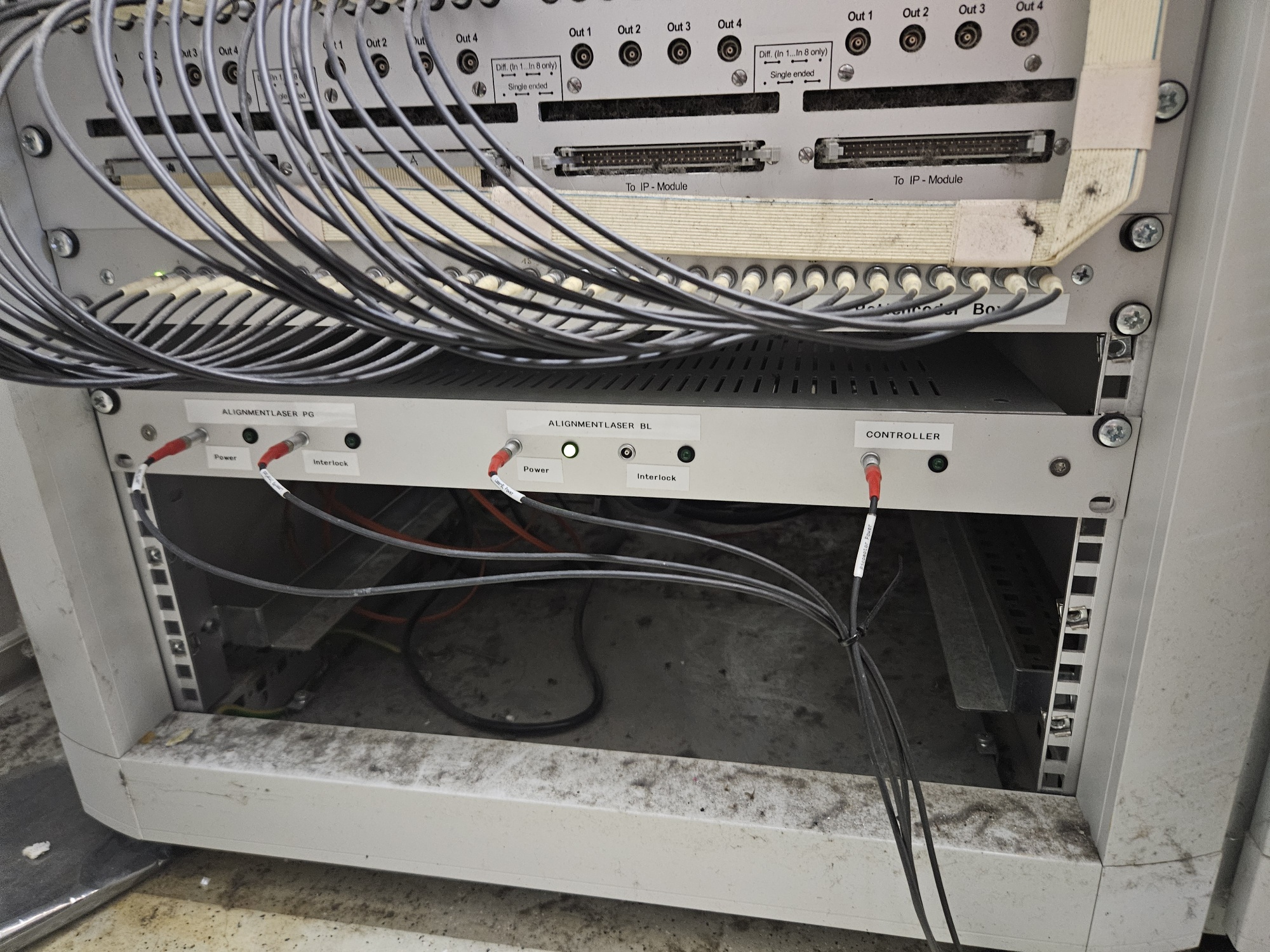
BDAAlignmentLaserBox
Last modified by sndueste on 2024/06/26 14:37
BDA-Alignment-Laser
Wiring Scheme of BDA-Alignmentlaser-Box
Below you can see the wiring scheme for the two alignment lasers ("Laser PG" and "Laser BL") and the controller for the picomotor actuators which can be found in the beam distribution area.
The relays will switch when given a 12 Volts signal.
The power supply unit inside the box is a "MTMKE 02" by "Kniel" (catalog number: 227-430-08).
It has three output voltages:
- A1 = 5V, 3A
- A2 = 15V, 0.5A
- A3 = 15V, 0.5A
For further details see DESY Lagerkatalog (item number 27 179; unit D; page 51).
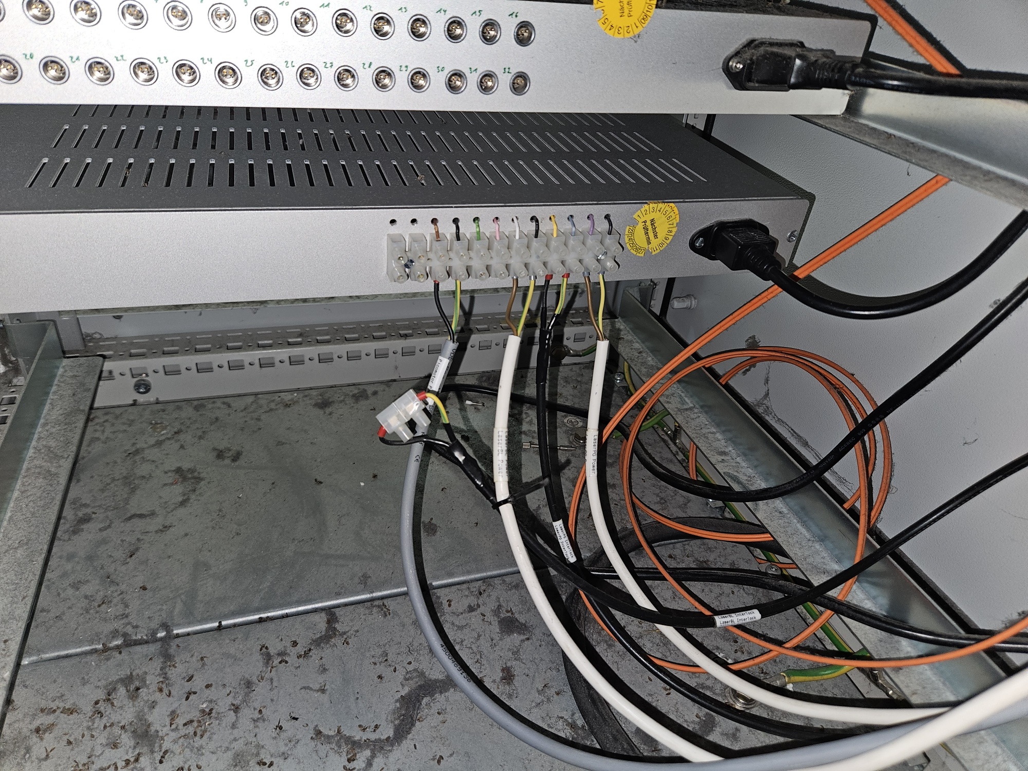
* BDA_Alignmentlaser_Box.gif: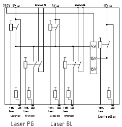
Backplane of the BDA-Alignmentlaser-Box
- BDA_Alignmentlaser_Box_Backplane.gif:

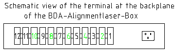
Terminal-No. | Signal |
|---|---|
1 | Power PG-Laser: GND |
2 | Power PG-Laser: +5V |
3 | Interlock out (GND) |
4 | Interlock in |
5 | Power BL-Laser: GND |
6 | Power BL-Laser: +5V |
7 | Interlock out (GND) |
8 | Interlock in |
9 | Power Controller: GND |
10 | Power Controller: +15V |
11 | --- |
12 | --- |
front