Luxor Spectrometer
To the commissioning of TTF phase II a spectrometer is placed inside the tunnel near the beam dump. It shall help to adjust beam parameters whilst the full diagnostics in the hall is not in place yet. Measurements are possible without getting the beam trough the long section of the petra crossing, several apertures for differential pumping etc.
The spectrometer is provided by uni Padova.
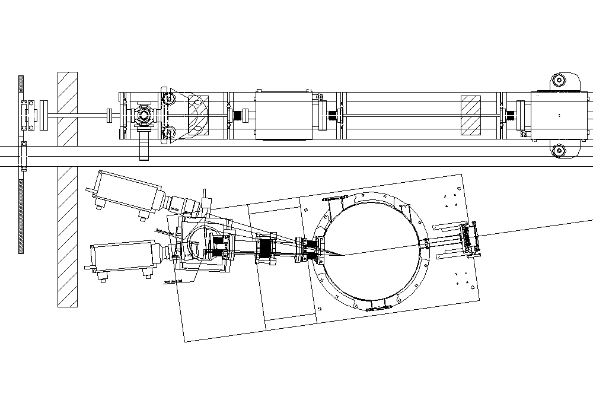
The placement could be as follows:

Note the following:
- Here is a
- The slit is mounted with beam direction reversed (Beam entering the side where it shall exit). This has to be fixed. The slit edges can not be removed (and turned around), thus the whole slit system has to be mounted the other way round.
- Problem: A 5 way cross is to be installed on the visible light beamline just where the camera is now. It will be used to set up the visual light beamline with a screen and camera. It should be move somewhat upstream.
- Problem 2: There have to be pumping ports for both the visual and fel light beamlines. Solve this (together with problem 1) in dialog with U.Hahn. (Fini, Meeting Tuesday)
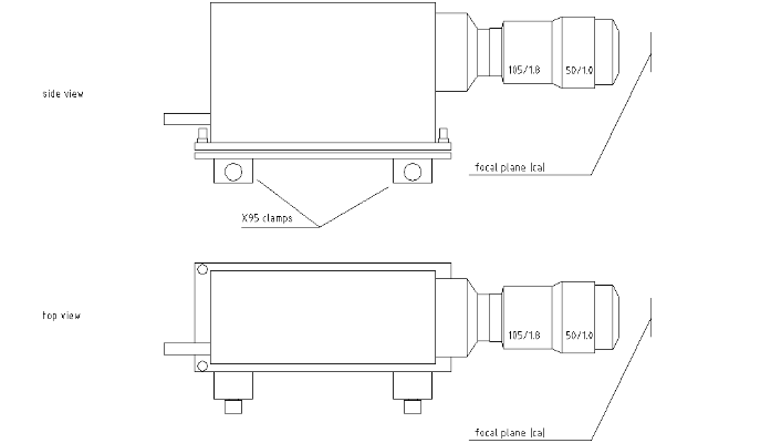
- I dont know the exact focal distance of the tandem optics (used f105/1.8 & f50/1.0). Christopher and Tom did some measurements on that. I approximated it to 40 mm measured from the lens' glas. Should be cross checked.
- Check possibility to move lead wall downstream right next to the tube holder.
Here is , the drawing of the NanoStar camera (bigger and ).

This is the camera with with a mirror in the middle.
Here are photos of the nanostar with tandem optics: and .
The slit system looks like this: and .
#Trash.MinutesMeetingNotes
Metting in Padova Oktober 2003
The following items were given to the LUXOR group:
- Slit system complete with bypass valve and CF40 blind flange
- Slit observation chamber with CF16 window and CF16 blind flange
- Slit controller including cables to slit system
- Screen flange with CF63 window
- Old screen flange with CF100 window and screen
- Screen flange holder system with two X95 rails
- Screen mirror box including mirror and X95 holder
- Lenses: 50mm 1:1.0 and 105mm 1:1.8 with transport boxes
- PCO DiCam pro with power supply and fibre obtical cable
- LaVision camera controlling computer (Win98) with camera card (without dongle)
- Keyboard and mouse
- 2 small X95 clamps, support ball
- 2 grey Alibert boxes with lid, 1 green small box (for camera), 1 small transport cart
Items still at Desy:
- Translation stage with stepper motor (sent in 2003)
- Linear encoder
Discussion Results:
- The spectrometer beamheight is 107 +- 2 cm. We need a support (concrete block) of 45 cm height.
- A linear encoder is to be fitted to the translator to get a step motor independent calibration.
- Calibration itself is checked after spectrometer arrived at Desy.
- Rough alignment is done with one theodolite looking on entrance slit and a mark (spike) on the spectrometer chamber (to be mounted).
- Spectrometer is fixed to the ground with paws.
- Fine alignment is done with alignment laser and 0th order.
- Spectrometer is pumped at the moment with 500l/s turbo pump. We change that to ion pump. Flange is ISO-K 160. Adaptor for CF supplies Desy.
- A (possibly) smaller turbo pump is fitted to one ISO 63 flanges on the side of the spectrometer. Again adaptor to CF, valve and turbo pump itself are supplied by Desy. We intend to use the items from old spectrometer again.
- Screen flange is adapted to ISO.
- Screen holder is modified with teflon ring.
2014 we have severe problems that the spectrometer delivers always double peaks
here the on the topic
Attachments:
